You plan temporary works to control groundwater because you need stable excavation faces, safe working conditions, and predictable schedules. Few systems give you as much control and speed as wellpoint dewatering. When you design it well, you lower pore pressure, keep fines out of the system, and move only the water you must. Poor design does the opposite and turns into noise, fuel burn, and turbidity complaints.
This guide takes you from inputs to pump choice, with practical checks you can apply on day one of planning and again at startup. It reflects field practice that works on silty sands and medium sands where wellpoints shine, and it flags where you should switch to deep wells or other methods.
What Is Wellpoint Dewatering (When to Use It)
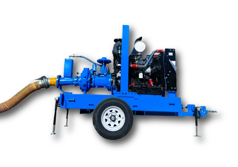
Wellpoint dewatering uses a series of small-diameter screened points connected to a header pipe and a vacuum-capable pump. The system creates suction along the header, drawing water through each wellpoint screen and lowering the groundwater table to a target level.
You use it when:
- The drawdown per stage is 3 to 5 m, with a practical limit near 6 m at sea level due to suction limits.
- Permeability k is high enough to yield to small-diameter screens, typically k from 1×10^-5 to 1×10^-3 m/s. Medium to fine sands and sandy silts respond well.
- The excavation footprint is long and shallow, trenches, utility corridors, or basements with large perimeters.
You avoid it or use staged systems when k is very low or drawdown is deeper than a single-stage vacuum can support. You also avoid wellpoints in gravels where high inflow and air entrainment overwhelm small screens and create chronic vacuum loss. In those conditions, deep wells with submersibles or ejector systems are better.
Strengths you can count on:
- Rapid installation and quick priming
- Uniform drawdown along linear work
- Good control of pore pressure in the upper aquifer
- Incremental staging as excavation progresses
Tradeoffs to plan for:
- Suction limit requires multiple stages for deep cuts
- Air leakage sensitivity at fittings and risers
- Sand carryover risk if slot size or filter pack selection is poor
Design Inputs & Calculations
Sound design starts with a small set of numbers you trust. The best way to get them is test pumping close to your excavation and at the same depth you intend to install screens. Treat test pumping as your insurance policy.
Drawdown target
Define the required groundwater level relative to the working elevation. You want:
- Water level at least 0.5 to 1.0 m below subgrade for bearing and stability
- Deeper drawdown if you face seepage-sensitive soils or require a dry trench bottom for welds or connections
Call this target drawdown s. If you need more than 5 to 6 m, plan two stages of wellpoints or combine with sump pumping inside a cut-off.
Permeability k and transmissivity
From test pumping and piezometer response, extract:
- Permeability k [m/s] for the formation around the screen
- Transmissivity T [m^2/s] if the aquifer thickness is known
Lab grain-size curves help you set screen slot size and filter pack, but you size the system by field k and T. Expect:
- Silty sand: k ≈ 1×10^-5 to 5×10^-5 m/s
- Fine to medium sand: k ≈ 1×10^-4 to 1×10^-3 m/s
Radius of influence R
Estimate the radius of influence for a single-stage wellpoint system using the Sichardt relation for unconfined conditions:
- R ≈ 3000 × s × √k (R in meters, s in meters, k in m/s)
This gives you a starting footprint for drawdown limits and highlights boundary effects from sheet piles, utility obstructions, or impermeable lenses that truncate R.
Total flow and flow per wellpoint
Approximate the total flow to the system using Dupuit assumptions for an unconfined aquifer. For a circularized influence zone:
- Q_total ≈ π × k × (H^2 − h^2) / ln(R/r_w)
Where:
- H is initial saturated thickness
- h is saturated thickness after drawdown
- r_w is an effective well radius for the header line or equivalent collector
- ln(R/r_w) is the influence term
For linear trenches, you can use the line-sink form per unit length q’ and scale by trench length L:
- q’ ≈ k × (H^2 − h^2) / (2 × s) [approximate]
- Q_total ≈ q’ × L
Field design often reverses this: start from expected wellpoint yield and pick spacing to achieve drawdown uniformity.
Typical sustainable discharge per wellpoint depends on k and drawdown at the screen:
- Silty sand: 0.3 to 1.5 m^3/h per point
- Fine sand: 1 to 2.5 m^3/h per point
- Medium sand: 2 to 4 m^3/h per point
Use the low end during early drawdown when air entrainment is highest, then expect a slight reduction as the drawdown curve stabilizes and inflows reduce.
Number and spacing of wellpoints
Set spacing to balance drawdown uniformity and manageable header losses:
- Typical spacing: 0.75 to 1.5 m for silty sands; 1.0 to 2.5 m for sands
- Closer spacing at corners, low points, and around obstructions
Steps:
- Compute Q_total to reach your target s across the footprint.
- Pick an initial spacing S from soil type and intended drawdown near the screen.
- Compute N ≈ Perimeter / S for a perimeter system, or N ≈ Length / S for a line.
- Check point load: Q_point = Q_total / N. Compare with the yield range for k.
- Iterate S and N until Q_point falls in a manageable range and the spacing provides a smooth drawdown curve without dead spots.
Apply a design factor of 1.2 to 1.5 on N to account for local variability, installation defects, or partial clogging during startup. Plan spare stub-outs on the header for infill points.
Screen slot size and filter pack
You control fines migration by matching slot size and pack to the soil:
- Use slot size D10 to D30 of the filter pack
- Pick filter pack gradation 4 to 5 times the native D15
- Install screens with 0.6 to 1.2 m length for shallow systems; place the screen fully below final drawdown with at least 0.5 m cover
Add a sump/strainer on the header near the pump to collect migrating fines and protect the air/water separator.
Header Layout & Piping
Your header has one job: move water and air from many small points to a pump that can handle both. Good layout minimizes air leakage, keeps vacuum uniform, and keeps friction losses in check.
Riser and screen placement
- Set the screen tip 0.5 to 1.0 m below the final target water level so the screen remains submerged under vacuum.
- Keep uniform riser length where possible to reduce variations in local head loss.
- Use reliable connectors at each riser with a non-return/check valve that closes cleanly during pump shutdown to preserve prime.
Header diameter and arrangement
- Place the header slightly sloped toward the pump to encourage air migration to the separator.
- Keep header velocities below 1.5 to 2.0 m/s to limit friction loss and entrained air.
- Use short branch takeoffs and swept fittings to reduce turbulence and air binding.
- Minimize high points where air can collect; vent these points during startup.
A quick selection guide helps match header diameter to flow and wellpoint count. Values below assume water at 20 C and target velocity near 1.5 m/s.
| Header ID (mm) | Flow range (m^3/h) | Typical wellpoints supported | Typical spacing note |
|---|---|---|---|
| 100 | 15 to 40 | 10 to 25 | Short runs or low k |
| 150 | 40 to 90 | 20 to 45 | Most trench work |
| 200 | 90 to 160 | 40 to 80 | Long perimeters |
| 250 | 160 to 250 | 70 to 120 | Large basements |
Check friction loss using Darcy–Weisbach or Hazen–Williams. For vacuum systems, every kPa of loss is precious. Keep header friction below 5 to 8 m of water column equivalent over the run to avoid starving the upstream points of vacuum.
Fittings, friction, and valves
- Use full-bore valves on discharge lines. Avoid throttling on the suction side.
- Seal threaded joints with PTFE tape and anaerobic sealant; vacuum makes even small leaks significant. Test with a vacuum hold test before startup.
- Keep flexible hose runs short. Each corrugated length adds turbulence and friction loss.
Discharge arrangement
Plan discharge from day one:
- Route flows through a sedimentation tank or lamella unit sized for at least 30 minutes of residence time when turbidity risk is high.
- Install a sampling point downstream of sedimentation for compliance checks tied to the discharge permit.
- Provide a high-flow bypass around sedimentation with auto-divert on turbidity alarm to avoid flooding the excavation while you troubleshoot.
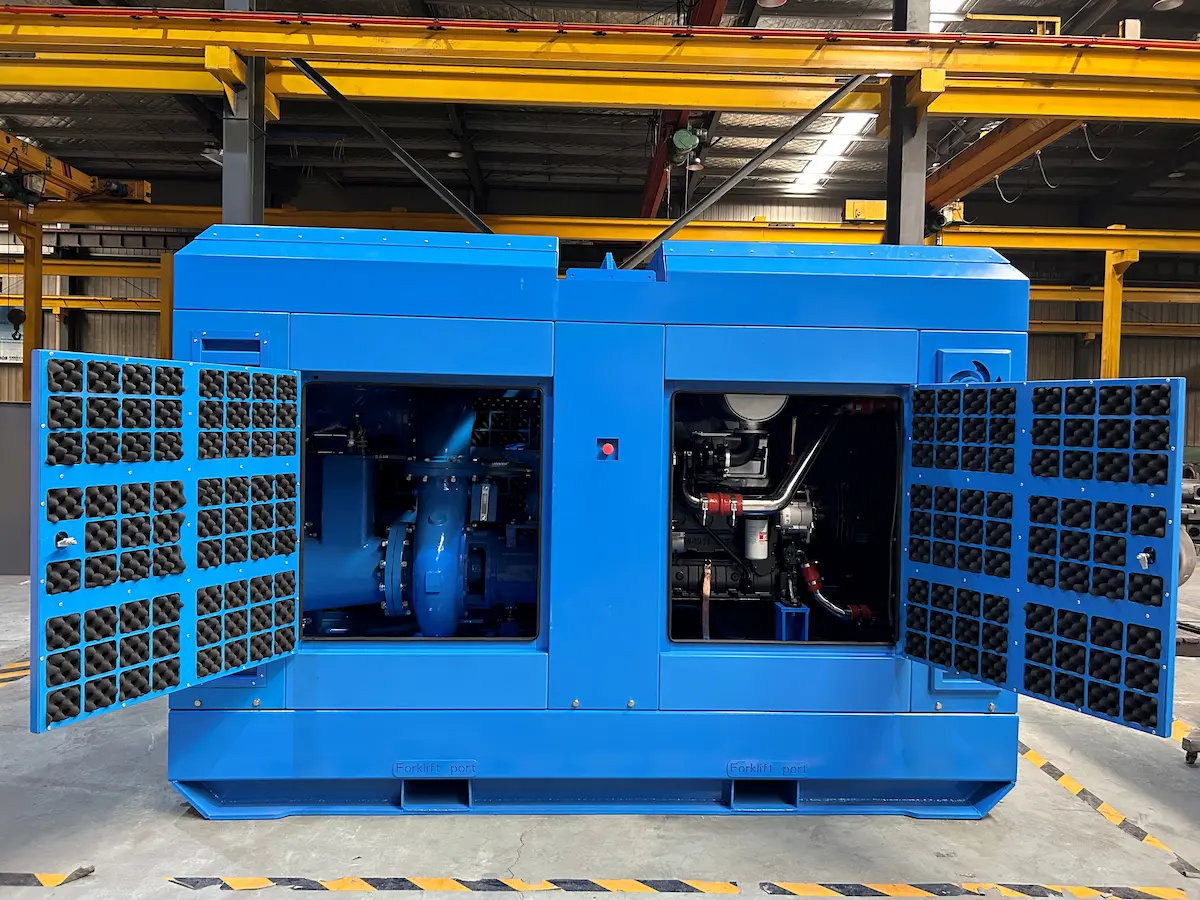
- Consider noise & fuel efficiency by locating the pump in a baffled acoustic enclosure and running at the lowest RPM that sustains vacuum and flow.
Pump Selection for Wellpoint Dewatering
All the field problems you see with wellpoints trace back to the wrong pump or a good pump used outside its envelope. You want a pump that moves water and air together for as long as air persists in the system.
Pump types
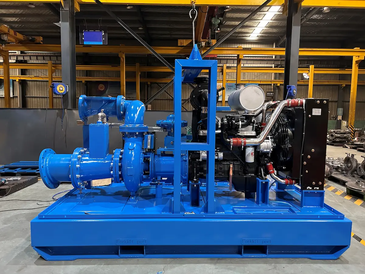
- Vacuum-assist centrifugal with air/water separator: A liquid end provides flow, a separate vacuum module removes air through an air/water separator and non-return/check valve. This is the standard for wellpoints.
- Self-priming centrifugal only: Works once the system is fully flooded with minimal air. Poor choice for wellpoints where air-handling during initial drawdown and ongoing air leakage are constant.
Key differences that matter in the field:
| Feature | Vacuum-assist centrifugal | Self-priming centrifugal |
|---|---|---|
| Air-handling continuous | Yes, 50 to 150 cfm common | Limited, intermittent |
| Vacuum level | Up to 85 to 90 kPa vacuum | 40 to 60 kPa typical |
| Priming time | Fast on long headers | Slow, often stalls |
| Tolerance to air leakage | High | Low |
| Best use | Wellpoints and mixed air/water | Sumps, flooded suction only |
Air-handling capacity and vacuum level
Air-handling capacity keeps the header under vacuum during early drawdown and while air leaks persist at risers or joints. Target a vacuum module that can pull at least 75 cfm for mid-size systems, with 100 to 150 cfm for large perimeters. Aim for stable vacuum near 80 to 85 kPa on the separator gauge during steady state. If you see chronic vacuum below 70 kPa with frequent cycling, you are under-pumped or leaking air.
Total dynamic head, suction lift, and NPSHa
Compute TDH as the sum of:
- Static lift from normal water level at the wellpoint screen to the pump centerline
- Discharge static head at the outfall
- Friction loss in the header, risers, fittings, and discharge
- Minor losses at separator and valves
Vacuum sets the suction lift. At sea level, absolute maximum theoretical lift is near 10.3 m of water, but real systems top out near 6 to 7 m due to vapor pressure, losses, and temperature. Keep the pump as low as possible relative to the wellpoint screens to maximize NPSHa and keep cavitation away. Verify that the air/water separator and the non-return/check valve have low loss at your design flow.
Power and fuel
Select a drive that meets peak air-handling and water flow without constant high RPM. Advantages you gain with the right package:
- Fuel efficiency with variable speed control and auto-sleep on stable vacuum
- Lower noise with proper enclosure and slower running
- Remote telemetry to adjust setpoints and catch trends in priming time and cycling
Gas or diesel both work. For urban sites, Tier 4F diesel in an enclosure with aftertreatment gives you fewer complaints. Electric drives win on noise and running cost when available power and permits allow.
Practical sizing workflow
- From your design, estimate Q_total and expected Q at startup when air is highest. Include a 20 percent margin.
- Choose a vacuum-assist pump with air-handling at least equal to the startup air load. If in doubt, pick the next size up; air is the limiter.
- Check the water performance curve for the pump at your TDH. Ensure the operating point lies well within the efficiency plateau, not near shutoff or runout.
- Confirm suction lift at your site elevation and temperature. Keep drawdown per stage under 5 to 6 m and consider two stages if you need more.
- Size the fuel tank or power supply to run through the night with alarms tied to vacuum level, high temperature, and low fuel.
Startup indicators to watch
- Priming time: Long priming indicates leaks or undersized air-handling.
- Stable vacuum: A steady reading with small oscillations indicates a sealed header.
- Separator performance: Continuous air bleed without large slugs reduces pump cycling and protects the liquid end.
FAQ
Q1: How do you install and test a wellpoint header before excavation?
A: Jet in each wellpoint to design depth, connect risers with check valves, assemble the header with all caps and gaskets, then perform a vacuum hold test. Pull down to at least 70 kPa vacuum and hold for 15 minutes. If decay exceeds 10 kPa, hunt for leaks with soapy water at joints and riser valves.
Q2: What are the first checks when you lose prime or see unstable vacuum?
A: Isolate the header in segments and recheck vacuum. Inspect non-return/check valves at risers for debris. Tighten or reseal threaded joints. Verify the air/water separator drain and float. Increase air-handling rate on the vacuum module if available. Persistent cycling points to air leakage, not lack of water.
Q3: How do you choose screen slot size and avoid sand carryover?
A: Base slot size on a graded filter pack that retains the native D85. Use a pack 4 to 5 times the native D15 and pick slots between the pack’s D10 and D30. During startup, throttle discharge briefly to prevent high entrance velocities until the drawdown curve stabilizes. Install a sump/strainer upstream of the pump.
Q4: How do you stay compliant on discharge quality and turbidity?
A: Route discharge to a sedimentation tank or clarifier sized for expected flow. Sample at a dedicated port before the outfall. Keep a standing discharge permit on site and record daily flows and turbidity. Add a bag filter or sand filter if limits are tight or if you see fines in the separator sight glass.
Q5: What is the role of test pumping before full installation?
A: It gives you field values for permeability k and transmissivity, confirms the radius of influence, and reveals how fast the drawdown curve forms. You also learn expected wellpoint spacing, priming time, and total flow. These data simplify pump selection and size your header accurately.
Q6: How do you estimate friction loss without full modeling?
A: Keep velocities in the header around 1.5 m/s and assume 2 to 6 m of loss per 100 m of pipe for smooth runs with few fittings. Add 0.5 to 1 m per elbow and 1 to 2 m for the separator and valves. Verify with a quick Darcy–Weisbach check when the layout is fixed.
Q7: What if your excavation needs more than 6 m of drawdown?
A: Use two stages. Install the lower stage first with points set below the final water level, then add an upper stage near mid-height. Offset headers to avoid interference, and use separate pumps so each stage maintains its own vacuum.
Q8: How do you control noise & fuel efficiency on tight urban sites?
A: Pick variable speed vacuum-assist pumps with acoustic enclosures, site them behind barriers, and set control bands for vacuum that avoid rapid cycling. Reduce header leaks to cut air-handling workload. Share a discharge line between stages to reduce above-ground pipe runs that radiate noise.
Q9: What does a healthy wellpoint system look like during steady operation?
A: The pump runs at a stable RPM, vacuum holds near 80 kPa with slow modulation, discharge is clear after sedimentation, and piezometers show a flat drawdown curve aligned with your target. You rarely see air slugs in the separator sight glass once the system settles.
Q10: How do you plan for redundancy?
A: Provide quick-connects for a standby pump, leave two spare stub risers per 50 m of header, and keep spare check valves and gaskets on hand. Wire alarms to your site telemetry so a vacuum drop or pump fault reaches the night crew before water rises.