Sizing a dewatering pump feels straightforward until you try to turn a rough plan into a reliable duty point. You need to move a known flow against a known head, keep the pump out of cavitation, pass the solids your site throws at it, and start it without babysitting. Getting those pieces right pays back with stable drawdown, improved performance, fewer maintenance stops, and consistent production.
The steps below give you a clear path from site conditions to a defensible selection.
Define the duty point: flow and head
Start by locking in the flow and the total dynamic head your system must deliver. Everything else hangs on these two numbers.
- Flow: Combine groundwater inflow, run-off, process water spills, and contingency. If you’re feeding multiple sources to a sump or header, use a diversity factor, not a straight sum, unless peak coincidence is expected.
- Head: This is the total dynamic head (TDH), not just vertical lift. TDH includes static lift, discharge elevation, friction in pipe and hose, and minor losses in fittings and valves.
A practical way to set flow:
- Calculate base inflow from hydrogeology or past data.
- Add peak rainfall or storm return period if you’re running an open pit.
- Apply a margin. Many teams carry 10 to 25 percent to cover variations or screen blinding.
Use duty/standby logic on critical lines. Duty/assist is common where level control modulates flow.
Total dynamic head (TDH) step by step
You can write TDH as:
- TDH = Static head + Friction losses (suction + discharge) + Minor losses + Exit or entry losses
Break it into pieces you can check.
Static head
- Surface pump with suction lift: Static head = discharge elevation above pump datum + suction lift (vertical distance from liquid level to pump centerline)
- Flooded suction or submersible: Static head = discharge elevation above pump datum minus liquid level at pump
Account for level variation. Set duty at the lowest expected suction level and highest discharge level if drawdown and stockpile ramps are large.
Friction losses
Pick a method and stick with it. Darcy–Weisbach works across conditions and diameters.
- Darcy–Weisbach: h_f = f*(L/D)*(v^2/(2g))
- f from Moody chart or Swamee–Jain, using Reynolds number and roughness
- Hazen–Williams can be acceptable for water in larger pipes. Choose a conservative C for used pipe or hose.
Velocity targets:
- Water with light silt: 1.5 to 2.5 m/s keeps material moving and friction reasonable
- Slurry service: 2.0 to 3.0 m/s to avoid settling
- Suction lines: keep below about 1.8 m/s to limit NPSH losses
Minor losses
Minor losses come from bends, tees, valves, reducers, strainers, and entrances. Either use K-factors or equivalent lengths. Be consistent.
Common K-factors for water service:
| Fitting/Component | K (typical) |
|---|---|
| Standard 90 degree elbow | 0.9 to 1.5 |
| Long radius 90 degree elbow | 0.5 to 0.75 |
| 45 degree elbow | 0.4 to 0.5 |
| Tee, through run | 0.6 to 1.0 |
| Tee, branch | 1.8 to 2.0 |
| Swing check valve | 2.0 |
| Gate valve (open) | 0.15 |
| Ball valve (open) | 0.05 |
| Sudden contraction | 0.4 to 0.8 |
| Sudden expansion | 1.0 |
| Suction entrance (square) | 0.5 |
| Suction strainer | 1.0 to 2.0 |
If you’re using layflat hose, treat couplings as short contractions and expansions. Hose corrugation increases friction compared with steel pipe.
Exit and free discharge
If you discharge to atmosphere, include the velocity head if your calculation method requires it. Many vendors fold this into minor losses at the discharge diffuser.
Reserve head
Carry a margin on TDH. Five to ten percent is typical for static systems with small variation. Use a bit more where suction levels swing or the line scales or sands up.
NPSH: avoid cavitation
Check net positive suction head available (NPSHa) against the pump’s required NPSH (NPSHr) at the duty flow.
NPSHa (meters of liquid) can be written as:
- NPSHa = Ha + Hs − Hv − Hf_suction
Where:
- Ha = atmospheric head at site (about 10.3 m at sea level, less at elevation)
- Hs = static suction head, positive if the liquid level is above the pump, negative if there is suction lift
- Hv = vapor pressure head of the liquid at operating temperature
- Hf_suction = friction loss in the suction line and fittings up to the impeller eye
Recommendations:
- Keep NPSHa at least 1 m above NPSHr for small pumps. Many engineers prefer 20 to 30 percent margin, more for non-condensable gas entrainment or warm water.
- Reduce NPSHr by selecting lower speed pumps. Trimming impellers changes the curve but does not fix an NPSH deficit if the speed stays high.
- Increase NPSHa by raising the liquid level, shortening or enlarging the suction line, removing restrictions, or reducing water temperature. In marginal cases, switch to a submersible or flooded suction.
Watch for off-design conditions. A throttled or partially clogged suction strainer can erase your NPSH margin in minutes.
Solids handling and pump type
Dewatering is rarely clear water. The dewatering process involves handling particle size, solids concentration, and abrasiveness, which drive pump type, materials, and expected service life.
- Particle size: Pick an impeller and casing that pass the largest occasional size. Vortex and recessed impeller designs pass large solids with lower efficiency. Semi-open impellers pass moderate solids with better efficiency.
- Solids concentration: For silt and fine sand under 5 percent by volume, dewatering pumps with robust clearances are fine. Above that, look at slurry pumps with thicker liners and slower specific speeds.
- Abrasiveness: High-chrome iron, duplex stainless, or rubber-lined slurry pumps extend life. Avoid sharp turns and sudden expansions near the pump.
- Induced wear: Higher velocities reduce settling but increase erosive wear. Find a balance.
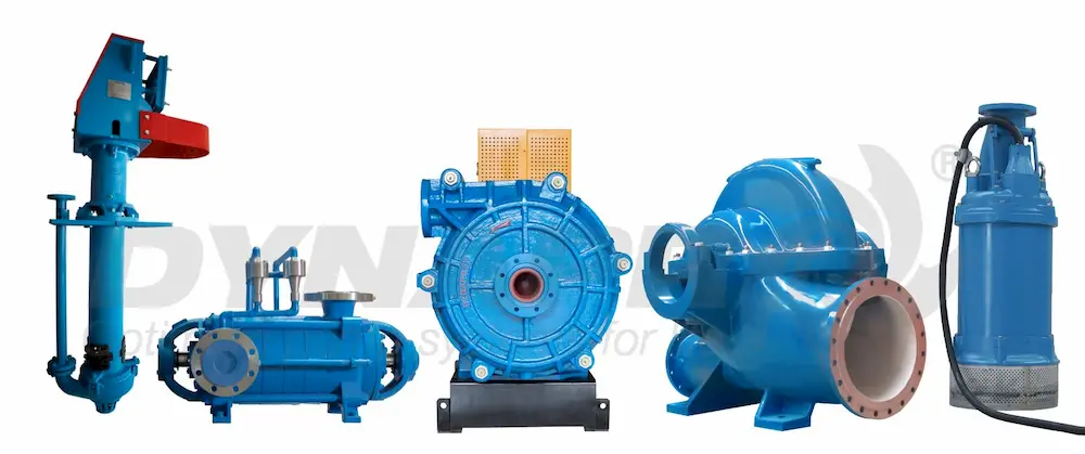
Pump types you’ll pick from:
- Vacuum-assisted auto-prime surface centrifugal: quick start, handles air, widely used for mobile pit dewatering
- Self-priming centrifugal: fixed installations with short suction lifts
- Submersible dewatering: with submersible pumps having a flooded impeller, good NPSH, simple setup, check cable management and submergence
- Slurry pumps: for higher solids and coarse particles
- Multistage centrifugal: high head with clear water or filtered flows
Priming systems: auto, venturi, vacuum
Getting air out of the suction line decides whether your first start is painless or painful.
- Auto-prime (vacuum assisted)
- A separate vacuum pump evacuates the suction line and casing. Starts quickly, copes with leaks and intermittent air. Best for mobile units and long, leaky suctions.
- Venturi or eductor priming
- Uses a jet pump to create low pressure and evacuate air. Simple and compact. Works well when suction lines are tight and short. Slower to prime if there are leaks.
- Self-priming casings
- The pump retains liquid in a priming chamber. Good for short lifts and short suctions. Not ideal for frequent dry starts without protection.
Pick the simplest dewatering process that tolerates your site’s conditions. If your suction line runs across blasted rock with couplings every 6 meters, vacuum assist saves time and improves performance.
Pipe sizing and velocity targets
Pipe diameter sets friction and the solids transport window. You pay for larger pipe up front or for smaller pipe in energy and maintenance.
- Aim for 1.5 to 2.5 m/s in discharge lines for dewatering with light solids
- Keep suction below about 1.8 m/s to preserve NPSH
- For slurries with sand, 2.0 to 3.0 m/s helps avoid deposition
If space allows, step up one size on suction hoses. Use full-bore valves where possible.
Power and efficiency
Once you have flow and TDH, size the driver.
- Hydraulic power (kW) = ρ × g × Q × TDH / 1000
- Brake power (kW) = Hydraulic power / Pump efficiency
- Motor power (kW) = Brake power / Drive efficiency
Assumptions:
- Water density near 1000 kg/m³
- Pump efficiency varies: trash pumps around 55 to 70 percent, slurry pumps 40 to 60 percent, multistage clear water 70 to 82 percent
- Engine and V-belt losses add 5 to 10 percent
Use the Pump curve at your duty point to read efficiency, NPSHr, and allowable solids.
Worked example 1: mobile surface pump from pit sump
Goal:
- Lift water with silt and 20 mm gravel from a sump to a discharge point 25 m above pump elevation
- Flow target 140 L/s (504 m³/h)
- 200 m discharge, 8 inch (203 mm) HDPE, 6 standard 90 degree elbows, one swing check, one gate valve
- Suction: 8 m of 8 inch reinforced hose, foot valve and basket, suction level 3 m below pump centerline at minimum
Step 1: Static head
- Suction lift = 3 m
- Discharge elevation above pump = 25 m
- Static head = 3 + 25 = 28 m
Step 2: Velocity and friction
- Pipe area for 203 mm ID: A ≈ 0.0324 m²
- Velocity v = Q/A = 0.14 / 0.0324 ≈ 4.32 m/s
- This is high. Consider upsizing if energy or wear is a concern. Keep for now to illustrate.
- Darcy friction for HDPE, f ≈ 0.018 at this Re (approximation)
- Discharge friction: h_f = f*(L/D)(v²/(2g)) = 0.018(200/0.203)(4.32²/(29.81)) ≈ 0.0189860.951 ≈ 16.9 m
Step 3: Minor losses
- K total: 6 elbows at 1.0 = 6.0, swing check 2.0, gate 0.15, discharge diffuser 1.0, sum ≈ 9.15
- Minor head = K*(v²/(2g)) = 9.15*0.951 ≈ 8.7 m
Step 4: Suction friction and entrance
- Suction velocity same diameter, 4.32 m/s
- Hose length 8 m, f ≈ 0.03 (corrugation and hose roughness)
- h_f suction line = 0.03*(8/0.203)*0.951 ≈ 1.12 m
- Entrance K 0.5, foot valve and basket K 2.0, total K 2.5
- Suction minor = 2.5*0.951 ≈ 2.38 m
- Suction losses total ≈ 3.5 m
Step 5: TDH
- TDH ≈ Static 28 + Discharge friction 16.9 + Discharge minors 8.7 + Suction losses 3.5 ≈ 57.1 m
- Add 10 percent margin for uncertainty and siltation: ~63 m
Step 6: NPSH
- NPSHa = Ha + Hs − Hv − Hf_suction
- Ha ≈ 10.1 m (at 300 m elevation, rough), Hs = −3.0 m, Hv ≈ 0.3 m (20 C), Hf_suction ≈ 3.5 m
- NPSHa ≈ 10.1 − 3.0 − 0.3 − 3.5 ≈ 3.3 m
- At 140 L/s, many 8 inch trash pumps list NPSHr 3 to 5 m. Margin is thin or negative.
Actions:
- Upsize suction to 10 inch hose (reduce velocity to 2.8 m/s on suction). Suction loss falls roughly by factor (2.8/4.32)² ≈ 0.42. New suction losses near 1.5 m. NPSHa improves to ≈ 5.3 m.
- Or switch to submersible pumps in the sump. NPSH concerns vanish, but cable and submergence management required.
Selection:
- Pick a vacuum-assisted 8 inch auto-prime pump with best efficiency near 140 L/s and TDH around 63 m
- Check curve. If single-stage cannot meet 63 m at that flow, consider 6 inch high-head model with slightly lower flow or run two 6 inch pumps in parallel
Power:
- Hydraulic kW = 10009.810.14*63/1000 ≈ 86.5 kW
- At 60 percent pump efficiency, brake kW ≈ 144 kW. With engine and drive losses, select a 200 kW class diesel for altitude and heat derates.
Worked example 2: underground stage pump to surface
Goal:
- Sub-level pump at elevation −200 m lifts to surface tank at +20 m via 600 m of 6 inch schedule 40 steel pipe
- Flow 50 L/s (180 m³/h), water with fines under 1 percent by volume
- Submersible pump set 5 m below wet well low level (flooded suction)
Step 1: Static head
- Elevation rise from pump centerline (−205 m) to tank at +20 m is 225 m
Step 2: Pipe hydraulics
- 6 inch steel ID ≈ 154 mm, area A ≈ 0.0186 m²
- Velocity v = 0.05 / 0.0186 ≈ 2.69 m/s
- Friction factor f for old steel, assume 0.02
- h_f = 0.02*(600/0.154)(2.69²/(29.81)) ≈ 0.0238960.369 ≈ 28.8 m
- Fittings: 10 elbows, 2 gate valves, 1 check valve. K ≈ 101.0 + 20.15 + 2.0 = 12.3
- Minor loss = 12.3*0.369 ≈ 4.5 m
Step 3: TDH
- TDH ≈ 225 + 28.8 + 4.5 ≈ 258.3 m
- Add 5 percent margin: 271 m
Step 4: NPSH
- Flooded suction, short suction piping, low temperature water
- NPSHa is high; submersible pump NPSHr is usually low. Cavitation risk is minimal.
Selection:
- Multistage submersible or vertical turbine capable of 50 L/s at ~271 m
- Efficiency of multistage in this range 70 to 80 percent
Power:
- Hydraulic kW = 10009.810.05*271/1000 ≈ 132.8 kW
- At 75 percent pump efficiency, brake kW ≈ 177 kW. Accounting for motor and cable losses, a 200 kW motor is appropriate. Check voltage drop on 600 m feeder.
Notes:
- Consider staging via an intermediate tank if power availability or starting current is limited.
- Verify transient control. Long rising mains with check valves can see surge on power loss. Add air valves and a surge analysis.
Worked example 3: wellpoint system with vacuum-assisted pump
Goal:
- Perimeter wellpoint ring around a shaft collar
- 40 wellpoints, each drawing 0.35 L/s at target drawdown
- Header: 200 m of 6 inch HDPE to a pump set 1 m above grade
- Expect air carryover and occasional sand
Flow and air:
- Total flow 40 × 0.35 = 14 L/s (50.4 m³/h)
- Air entrainment can be significant during start and as water table drops. Assume 100 to 200 scfm of air at pump suction during initial drawdown.
Head:
- Static head small. Assume lift from wellpoints to header is under 4 m and discharge to a nearby ditch with 3 m elevation gain
- Friction at 14 L/s in 6 inch HDPE is minor (v ≈ 1.27 m/s), h_f over 200 m with f=0.018 gives ≈ 1.9 m
- Fittings and check valve add another 1 m
- TDH around 3 m static + 1.9 m friction + 1 m minors = 5.9 m. Use 8 m duty.
Priming system selection:
- Venturi priming struggles with sustained air volumes from wellpoints
- Vacuum-assisted auto-prime handles continuous air, keeps prime through level swings, and tolerates leaks
Pump:
- Choose a 6 inch vacuum-assisted pump with a solids-handling impeller that maintains 14 L/s at 8 m TDH and can evacuate 100 to 200 scfm of air while still moving water
- Check curve for air handling performance. Many manufacturers provide air-water performance maps.
NPSH:
- Suction lift near 4 m with small line losses. NPSHa ≈ 10.1 − 4.0 − 0.2 − 0.3 ≈ 5.6 m at sea level, adequate for low flow rate. Keep suction velocities low and use a large header to limit losses.
Operational tips:
- Install a good sand separator upstream if sand carryover is expected
- Keep screen cleaning tools on site. Screen blinding is the top cause of flow decline
Practical rules you can apply today
- Fix flow, then validate it with a low-risk field test or trial pump if the stakes are high
- Keep suction lines short, straight, and one or two sizes larger than discharge
- Size for the lowest sump level and the highest discharge elevation you expect
- Keep discharge velocities near 2 m/s unless solids transport needs a higher value
- Carry a TDH margin. Friction always grows in real systems
- Verify NPSHa exceeds NPSHr with margin at duty and near-shutoff
- If air is part of the system, pick vacuum assist over venturi
- For coarse solids, favor recessed or vortex impellers, accept the efficiency trade
- Don’t forget transients. Long lines and power trips create surge loads
Validation checklist before you approve a pump
Use this short list to reduce surprises:
- Duty point
- Flow with margin defined and reviewed with operations
- TDH broken into static, friction, and minor losses with sources cited
- NPSH
- NPSHa calculation with atmospheric head at site, vapor pressure at temperature, suction friction, and suction lift
- Compare to NPSHr at duty on the vendor curve with margin noted
- Hydraulics
- Pipe sizes, materials, lengths, and roughness documented
- Velocities within recommended ranges for solids and suction
- Fitting count and K-factors listed
- Selection
- Pump curve shows duty point in the preferred efficiency band
- Solids passage and material of construction match site solids
- Priming method selected for the air expected
- Motor or engine sized with efficiency and derates applied
- Operations
- Control philosophy (level control, duty/standby, auto start)
- Protection (dry run, thermal, phase loss, seal monitoring)
- Access for maintenance and safe handling of hoses and cables
- Transients and safety
- Check valves, air valves, and surge relief reviewed
- Start and stop procedures agreed, especially for long lines
Short FAQ
Q: How much head margin should you add?
A: Five to ten percent covers normal uncertainty in static levels and minor friction variance. If the suction level swings widely or the line is prone to scale or sand, push to 15 percent.
Q: What’s the fastest way to cure cavitation on a surface pump?
A: Lower the pump closer to the water, enlarge and shorten the suction line, clean the strainer, slow the pump if possible, or switch to a submersible or flooded suction. Verify NPSHa against the curve.
Q: What pipe size should you start with for mobile dewatering?
A: Aim for 2 m/s in the discharge at duty flow, then round up to the nearest standard hose or pipe. Increase one size on suction whenever layout allows.
A quick reference table for common choices
| Situation | Preferred pump type | Priming system | Notes |
|---|---|---|---|
| Mobile pit sump with gravel and silt | Trash or slurry centrifugal | Vacuum-assisted auto-prime | Large suction hose and strainer |
| Long static lift, clean water | Multistage centrifugal | Flooded or submersible | Higher efficiency, check surge |
| Wellpoint header with sustained air | Vacuum-assisted dewatering pump | Vacuum-assisted | Verify air-water map |
| Coarse solids, intermittent flow | Vortex or recessed impeller | Auto-prime or submersible | Accept lower efficiency |
| Short lift, fixed install, clear water | Self-priming end suction | Self-priming casing | Keep suction tight and short |
If you want a second set of eyes on a sizing package or a curve check, reach out, and tell us your flow, head, suction details, dewatering process, and solids. We’ll help you land on a reliable selection.