Sewer systems do not give you the courtesy of downtime. When you isolate a gravity main, rehabilitate a trunk line, or pull a lift station offline, flow keeps coming. Sewer bypass pumping is the controlled way to keep service continuous while you work, but the tolerance for error is close to zero. A missed peak, a failed prime, a loose coupling, or a telemetry blind spot can become a reportable sanitary sewer overflow (SSO) within minutes.
You are not just moving water. You are managing public health risk, environmental compliance, and round-the-clock reliability under changing hydraulics, debris load, and weather.
What is Sewer Bypass Pumping? (Applications & Risks)
Sewer bypass pumping is the temporary diversion of sanitary sewage around a work zone, failed asset, or treatment unit by using portable pumps and a temporary pipeline to reconnect upstream flow to a downstream point. You typically plug or isolate the pipe segment, capture flow at an upstream manhole or wet well, then pump through a discharge manifold into the downstream sewer, force main, or an approved containment point.
This work looks simple on a sketch and gets complicated in the field. Your bypass must tolerate diurnal variability, wet weather spikes, ragging, intermittent air binding, and real-world constraints like road crossings, limited access, and nearby residents who will call about noise.
Your risk profile is also different from dewatering. A bypass failure is not a flooded excavation. It is raw sewage on pavement or in a waterway, with regulatory exposure and cleanup costs that scale fast.
After you map the flow path, it helps to frame risk in operational terms.
- Reliability threats: ragging and clogging, loss of prime, fuel starvation, control failure
- Hydraulic threats: underestimated peak daily flow, excessive friction losses, suction lift limits, air pockets at high points
- Site threats: traffic impacts at road crossings, vandalism, noise complaints without sound attenuation
- Compliance threats: SSO reporting triggers, spill migration, inadequate documentation and response time
Calculating Critical Flow: Dry Weather vs Wet Weather Peaks
You size the bypass for the flow you must not miss. That means you separate average flow from peak flow, then you decide what “peak” must mean for the job’s risk and duration.
Dry weather flow is your baseline sanitary contribution plus infiltration. It still peaks during morning and evening usage, and it can surprise you when large commercial contributors cycle discharges.
Wet weather flow adds inflow and rainfall driven infiltration. For many systems, that is the dominant driver for bypass sizing because it can multiply flow quickly and it often arrives with higher debris load, which affects solids handling and pump performance.
A practical approach is to build your design basis from multiple sources:
- Recent flow meter data at or near the bypass location (best input).
- Lift station run time and pump curve back-calculation if direct metering is limited.
- Known peaking factors from your utility’s historical patterns, confirmed against the basin’s I and I behavior.
- A conservative wet weather allowance when the bypass will be in place across storm season.
You then convert that design flow to a pump and pipe duty point using total dynamic head (TDH). TDH includes static lift (including discharge elevation back into the system) and friction losses through suction piping, discharge piping, fittings, valves, and manifolds. Long temporary runs, small diameters, and too many fittings can push friction head high enough that your “rated” pumps never reach the needed flow.
If your discharge returns to a force main or a pressurized structure, include required discharge pressure, not just elevation. If you are tying into a gravity manhole, validate that the receiving line can accept the flow without surcharging. A bypass that “meets capacity” but causes downstream surcharge still creates an overflow risk at the next weak point.
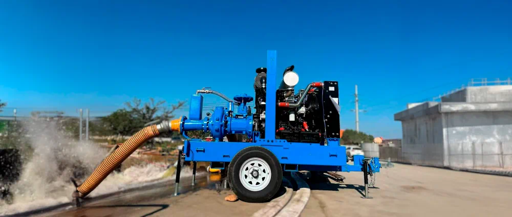
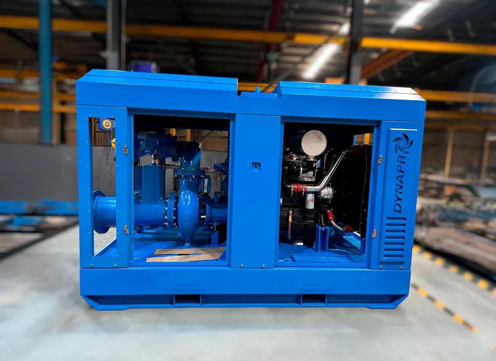
Pump Selection: Diesel Dry-Prime & Non-Clog Impellers
Bypass pump selection is about predictable performance under dirty, variable conditions. For municipal and contractor fleets, the workhorse is a fully automatic self-priming diesel dry-prime centrifugal pump with a true non-clog solids handling impeller.
You want a pump that can reliably pass at least 3-inch spherical solids and tolerate intermittent trash. Verify actual solids passage on the specific model, not just generic “trash pump” labeling. Ragging behavior varies widely across hydraulics and impeller geometry.
After you identify the duty point (flow at TDH), you also need to design for startup, restart, and upset conditions. Dry-prime capability matters because bypass systems frequently see intermittent air ingestion, level swings, and suction line disturbance during pump swaps or maintenance.
A short selection lens that holds up in the field looks like this.
- Duty point match on the curve
- Automatic priming and re-priming
- Solids passage rating
- Fuel burn and run time at expected load
- Sound attenuation package for nighttime or residential corridors
- Controls and instrumentation compatibility with your telemetry system
If you see chronic ragging in the basin, plan for it rather than hoping the pump “handles wipes.” Chopper pumps can be effective where rags and wipes dominate and where downstream piping can accept the altered solids profile. They are not a universal fix because they can increase maintenance complexity and can change what settles in the bypass line, but they can stabilize uptime where clogging would otherwise drive constant callouts.
Also treat suction conditions as a first-class constraint. A dry-prime pump’s suction lift limit is not a suggestion. High suction lift, long suction hose, leaking connections, and air entrainment all reduce effective capacity and can trigger repeated loss of prime.
Piping Setup: HDPE Fusion vs Quick-Disconnect Pipe
Your piping choice is a reliability choice. Every joint is a potential leak path, and every leak path is a potential SSO. At the same time, you still need a layout that can be built quickly, routed safely, and modified when the site changes.
For long-duration bypasses, fused HDPE is usually the preferred backbone because it reduces leak points and maintains pressure integrity when properly fused. For rapid mobilization or shorter work, quick-disconnect pipe systems can be the right tool, especially when you expect frequent configuration changes.
Before you pick, define the project realities: duration, diameter, working pressure, traffic exposure, and how often you will need to break and remake the line.
| Attribute | HDPE (butt-fused) | Quick-disconnect pipe (mechanical couplings) |
|---|---|---|
| Joint integrity | Highest when fusion is done correctly, effectively leak-free | Good when assembled correctly, more dependent on gasket condition and clamp torque |
| Best fit | Multi-week to multi-month bypass, larger diameter, higher consequence corridors | Emergency response, short duration bypass, complex routing that may change |
| Field changes | Slower to modify, requires cutting and re-fusion | Fast to modify, swap, or extend |
| Road crossings | Works well with preplanned routing and protection | Works well when you need fast reroutes around traffic staging |
| Maintenance load | Lower once commissioned | Higher inspection cadence because there are more joints |
Two layout details pay off regardless of pipe type. First, use a discharge manifold designed for balanced flow distribution and isolation, with valves that allow you to service one pump without interrupting others. Second, manage high points. Temporary bypass lines often snake around utilities and traffic control, so air pockets are common. Add air release at high points where it is safe to do so, and plan drain and flush points for controlled shutdown.
Lay-flat hose still has a place, but be honest about the risk. For long runs, long durations, and high public consequence locations, hose introduces more vulnerability to abrasion, puncture, and coupling issues than rigid pipe systems. If you use hose, protect it aggressively at crossings, limit exposure time, and increase inspection frequency.
Why N+1 Redundancy is Mandatory for Bypass Systems
If you size a bypass so that the running pumps barely meet peak, you have built a system that fails by design the moment one pump derates, clogs, or shuts down. That is why N+1 redundancy is the baseline expectation for safety-critical bypass work.
N is the number of pumps required to pass the design peak flow at the expected TDH. N+1 means you install one additional pump of equivalent capacity, staged and ready. If you need two pumps online to carry peak, you mobilize three, with one standing by.
This is not just extra iron on the ground. It is an operating philosophy:
- The standby unit is fully piped into the suction and discharge manifold.
- Controls are set so the standby auto-starts on level rise, pressure drop, or pump fault.
- You test the switchover under controlled conditions before you rely on it overnight.
If you are managing a fleet, N+1 also shapes how you standardize. Matching pumps simplifies parts, hoses, control panels, and operator training. Mixed pump models can work, but they complicate staging logic and can create unstable parallel operation if the curves do not play well together.
A bypass that cannot tolerate one failure is not a bypass plan. It is a spill plan.
Sewer bypass pumping readiness checklist (what you verify before startup)
You can have the right pumps and still fail on commissioning details. A short readiness check is where many SSOs are prevented.
Walk the system as if you are trying to break it, because the field will.
- Hydraulics: verify suction lift, check TDH assumptions against as-built routing, confirm receiving structure capacity
- Mechanical: confirm gasket condition, coupling engagement, valve positions, torque or locking pins as applicable
- Controls: validate float switches or transducers, simulate high level start for the standby unit, confirm alarm setpoints
- Operations: confirm fuel plan, run time, maintenance intervals, spare parts, and access for vacuum truck response
- Community: confirm sound attenuation approach, lighting, barriers, and traffic control at road crossings
Monitoring and Telemetry: Preventing Spills 24/7
If you are relying on “someone will notice,” you are accepting spill risk. A bypass needs continuous awareness, whether that is staffed watch, remote monitoring, or a hybrid.
A strong telemetry system watches the variables that change first when failure begins:
- Upstream level, ideally with redundant sensing in a critical manhole or wet well
- Discharge pressure on the manifold, which can indicate leaks, line breaks, or pump degradation
- Flow rate, where practical, to confirm capacity and detect silent underperformance
- Pump run status, fuel level (for diesel), engine alarms, and enclosure temperature
You then set alarm logic that reflects bypass behavior, not just generic pump alarms. High upstream level and low discharge pressure together is a different event than high level with normal pressure, and your response should differ.
Your notification chain matters. If alarms go to a single phone that goes silent at 2 a.m., you do not have monitoring. Escalation, acknowledgment, and dispatch procedures are part of reliability, just like pump curves.
Telemetry does not remove the need for physical inspection. It changes what you look for. You should still schedule line walks, verify road crossing protection, listen for changes in sound, and check for seepage at joints, but you are no longer blind between visits.
Safety Protocols and Spill Containment Plans
Bypass sites are a collision of hazards: pathogens, toxic gases, traffic, pressurized piping, noise, and occasionally confined space entry. Your safety program must treat wastewater exposure and spill response as primary risks, not side notes.
Start with controls that keep people out of harm’s way. Build stable pump pads, guard open manholes, secure piping against thrust loads, and route hoses and pipe so that a failure does not spray into pedestrian paths. Use critically silenced pumps or enclosures when you are near homes, hospitals, or night work zones, and confirm hearing protection requirements around the setup.
After you implement engineering controls, document and drill response actions so crews act quickly under stress.
- Exposure controls: PPE for splash risk, hygiene stations, decon procedure, vaccination policy as required
- Atmospheric controls: continuous H2S monitoring where gas can accumulate, ventilation plan for any confined space work
- Spill containment: secondary containment under fuel and engines, plugs and berms staged for low points, vacuum truck callout plan
- Response triggers: define when you shut down, when you divert to containment, who makes notifications, who documents volume and location
A spill containment plan should be written to match the site. A bypass crossing a creek needs different staging than one routed through an industrial corridor. What stays the same is the expectation that you can contain the first minutes of a release while you restore conveyance.
FAQ
1. What is the primary purpose of sewer bypass pumping?
To keep sanitary sewage flowing around a pipe segment, lift station, or treatment unit that is out of service so customers maintain service and you avoid an SSO.
2. How do you calculate the flow rate for a sewer bypass?
Use measured system data when available, then size for peak flow, not average, and confirm pumps can deliver that flow at the calculated TDH for the temporary routing.
3. What is N+1 redundancy in pumping systems?
It means you install one additional pump beyond what you need to carry peak flow, fully connected and set to start automatically if a running unit fails.
4. Why are Diesel dry-prime units preferred for sewer bypass over electric?
Diesel dry-prime units are self-contained, fast to deploy, and less dependent on site power reliability, which is valuable when failure consequences are severe.
5. What type of pipe is best for long-term bypass projects?
Butt-fused HDPE is often best for long-term bypasses because HDPE fusing creates leak-resistant joints and reduces maintenance at connections.
6. How do I prevent pumps from clogging with rags/wipes?
Select true non-clog impellers rated for large solids, manage suction conditions, stage a standby pump, and consider chopper pumps where ragging is persistent and well-characterized.
7. Do I need 24-hour monitoring for a bypass system?
If an overflow would be high consequence, yes. You can meet this with staffed watch, a telemetry system with alarms, or a hybrid, but you need continuous visibility and response.
8. What is the difference between dry weather and wet weather flow?
Dry weather flow is baseline sanitary plus infiltration with daily peaks; wet weather flow adds rainfall-driven inflow and infiltration, often driving the true design peak.
9. Can I use lay-flat hose for sewer bypass?
You can on short or lower-risk setups, but for long duration or high consequence corridors, rigid pipe or fused HDPE is usually more reliable.
10. How do suction lift limitations affect bypass design?
Excessive suction lift reduces priming reliability and capacity, raising spill risk; it can force you toward submersible pumps, different intake structures, or relocating pumps closer to the flowline.